By Josh D.
But first, a little history
Digital Equipment Corporation’s PDP-8 minicomputer was a small but incredibly flexible little computer. Introduced in 1965 at a cost of $18,000 it created a new market for small computers, and soon PDP-8s found themselves used for all sorts of tasks: Industrial control, laboratory data capture and analysis, word processing, software development, and education. They controlled San Francisco’s BART Subway displays, ran the scoreboard at Fenway Park and assisted in brain surgery.
They were also used in early forays into time sharing systems. Time-sharing stood in stark contrast to the batch processing systems that were popular at the time: Whereas batch processing systems were generally hands-off systems (where you’d submit a stack of punched cards to an operator and get your results back days later) a time-sharing system allowed multiple users to interact conversationally with a single computer at the same time. These systems did so by giving each user a tiny timeslice of the computer: each user’s program would run for a few hundred milliseconds before another user’s program would get a chance. This switching happens so quickly it is imperceivable to users — providing the illusion that each user had the entire computer to themselves. Sharing the system in this manner allowed for more efficient use of computing resources in many cases.

TSS/8 was one such time-sharing endeavor, started as a research project at Carnegie-Mellon University in 1967. A PDP-8 system outfitted with 24KW of memory could comfortably support 20 simultaneous users. Each user got what appeared to them as a 4K PDP-8 system with which they were free to do whatever they pleased, and the system was (in theory, at least) impervious to user behavior: a badly behaved user program could not affect the system or other users.
With assistance from DEC, TSS/8 was fleshed out into a stable system and was made available to the world at large in 1968, eventually selling over a hundred copies. It was modestly popular in high schools and universities, where it provided a cost-effective means to provide computing resources for education. While it was never a widespread success and was eventually forgotten and supplanted on the PDP-8 by single-user operating systems like OS/8, TSS/8 was a significant development, as Gordon Bell notes:
“While only a hundred or so systems were sold, TSS/8 was significant because it established the notion that multiprogramming applied even to minicomputers. Until recently, TSS/8 was the lowest cost (per system and per user) and highest performance/cost timesharing system. A major side benefit of TSS/8 was the training of the implementors, who went on to implement the RSTS timesharing system for the PDP-11 based on the BASIC language.”
Gordon Bell, “Computer Engineering: A DEC View of Hardware Systems Design,” 1978
It is quite notable that DEC made such a system possible on a machine as small as the PDP-8: An effective time-sharing system requires assistance from the hardware to allow separation of privileges and isolation of processes — without these there would be no way to stop a user’s program from doing whatever it wanted to with the system: trampling on other users’ programs or wreaking havoc with system devices either maliciously or accidentally. So DEC had to go out of their way to support time-sharing on the PDP-8.
PDP-8 Time-Sharing Hardware
In combination with the MC8/I memory extension (which allowed up to 32KW of memory to be addressed by the PDP-8), the KT8/I was the hardware option that made this possible, and was available on the PDP-8/I as an option at its introduction. The KT8 option was made available for the original PDP-8 around this time as well.
So what does the KT8/I do (in combination with the MC8/I) that makes time-sharing on the PDP-8 feasible? First, it provides two privilege levels for program execution: Executive, and User. The PDP-8 normally runs at the Executive privilege level — at this level all instructions can be executed normally. Under the User privilege level, most instructions execute as normal, but certain instructions are forbidden and cause a trap. On the PDP-8, trappable instructions are:
- IOTs (I/O Transfer instructions, generally used for controlling hardware and peripherals).
- The HLT (Halt) instruction, which normally stops the processor.
- The OSR and LAS instructions, which access the front panel’s switch register.
Under a time-sharing system such as TSS/8, the operating system’s kernel (or “Monitor” in TSS parlance) runs at the Executive privilege level. The Monitor can then control the hardware and deal with scheduling user processes.
User processes (or “Jobs” in TSS) run at the User level (as you might have guessed by the name). At this level, user programs can do whatever they want, but if one of the classes of instructions listed above is executed, the user’s program is suspended (the processor traps the instruction via an interrupt) and the PDP-8’s processor returns to the Monitor in Executive mode to deal with the privileged instruction. If the instruction is indeed one that a user program is not allowed to execute, the Monitor may choose to terminate the user program. In many cases, IOTs are used as a mechanism for user programs to request a service from the Monitor. For example, a user program might execute an IOT to open a file, type a character to the terminal, or to send a message to another user. Executing this IOT causes a trap, the Monitor examines the trapped instruction and translates it into the appropriate action, after which the Monitor resumes execution of user’s program in User mode.
Thus the privileged Executive mode and the unprivileged User mode make it possible to build an operating system that can prevent user processes from interfering with the functioning of the system’s hardware. The MC8/I Memory Extension hardware provided the other piece: Compartmentalizing user processes so they can’t stomp on other user programs or the operating system itself.
A basic PDP-8 system has a 12-bit address space and is thus capable of addressing only 4KW of memory. The MC8/I allowed extending memory up to 32KW in 4KW fields of memory — it did so by providing a three bit wide Extended Memory Address register (which thus provided up to 8 fields.) This did not provide a linear (flat) memory space: The PDP-8 processor could still only directly address 4096 words. But it did allow the processor to access data or execute instructions from any of these 8 fields of memory by executing a special IOT which caused future memory accesses and/or program instructions to come from a new field.
With this hardware assistance it becomes (relatively) trivial to limit a user program to stay within its own 4KW field: if it attempts to execute a memory management IOT to switch fields the KT8/I will cause a trap and the Monitor can either abort the user’s program or ensure that the field switch was a valid one (swapping in memory or moving things around to ensure that the right field is in the right place). (This latter proves to be significantly more difficult to do, for reasons I will spare you the details on. You’re welcome.)
This article’s supposed to be about running TSS/8 on a real PDP-8, let’s talk about that then shall we?
Where were we. Oh yes, TSS/8.
TSS/8 was initially designed to run on a PDP-8/I (introduced 1968) or the original PDP-8 (1965) equipped with the following hardware at minimum:
- 12KW of memory
- KT8/I and MC8/I or equivalent
- A programmable or line-time clock (KB8/I)
- An RF08 or DF32 fixed head disc controller with up to four RS08s or DS32 fixed head disks
Optionally supported were the TC08 DECtape controller and a DC08 or PT08 terminal controller for connecting up multiple user terminals. As time went on, TSS/8 was extended to support the newer Omnibus PDP-8 models and peripherals: The PDP-8/e (1970), 8/f, 8/m and the 8/a introduced in 1976.
TSS/8 used an RF08 or RF32 disc for storing the operating system, swapping space, and the user filesystem. Of these the most critical application was swapping: each user on the system got 4KW of swap space on the disk for their current job — as multiple users shared the system and there became more users than memory, a user’s program would be swapped out to disk to allow another user’s program to run, then swapped back in at a later time. Thus the need for fast transfer rate with minimal latency was required: The RF08 being a fixed-head disk had very little latency (averaging about 17ms due to rotational delays) and had a transfer rate of about 62KW/second.
Fixed head disks also had the advantage of being word addressable, unlike many later storage mechanisms which read data a sector at a time. This made transfers of small amounts of data (like filesystem structures) more efficient as only the necessary data needed to be transferred.
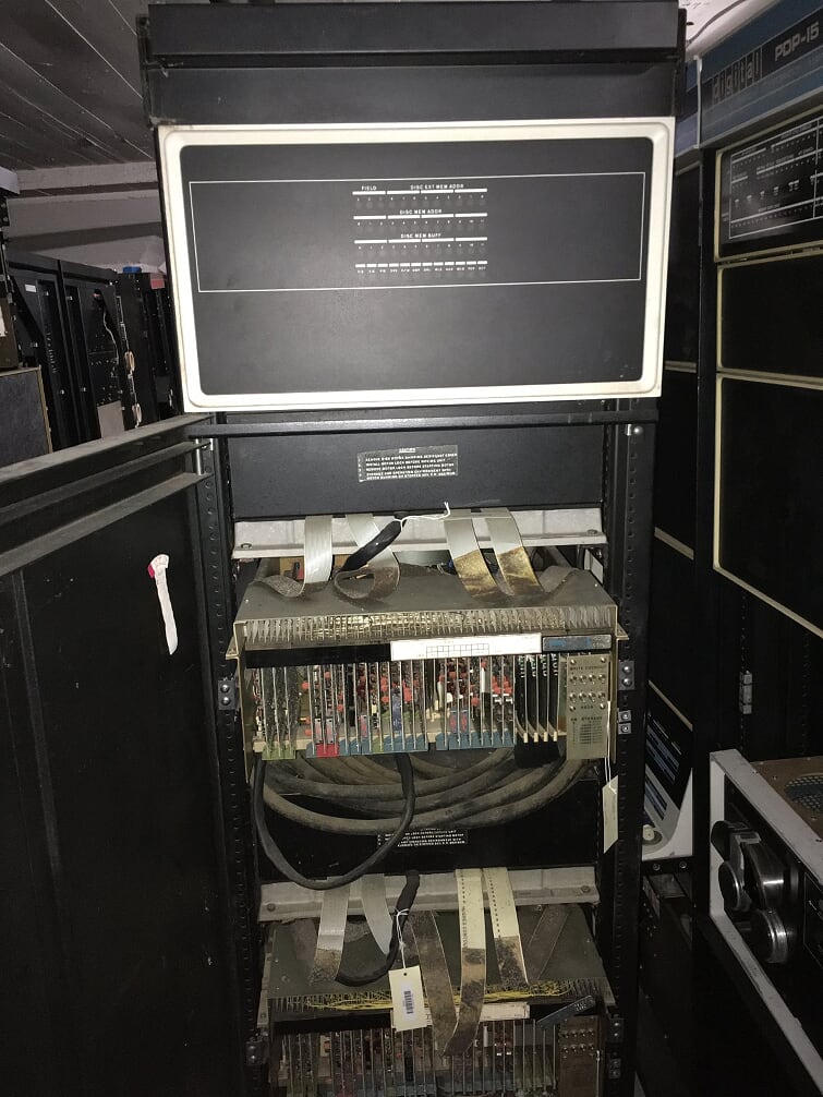 Our RF08 Controller with two RS08 drives (256KW capacity each)
We’ve wanted to get TSS/8 running at the museum for a long time. The biggest impediment to running TSS/8 on real hardware in this year of 2019 is the requirement for a fixed-head disk. There are not many RF08s or RF32s left in the world these days, and the ones that remain are difficult to keep operational in the long term. We have contemplated restoring a PDP-8/I and the one RF32 controller (with two RS32 discs) in our collection or building an RF08 emulator, but I thought it would be an interesting exercise to get it to run on the PDP-8/e we already have on exhibit on the second floor, with the hardware we already have restored and operational.
 LCM+L’s PDP-8/e. RK05 drive on the left.
Our 8/e is outfitted with an RK05 drive, controlled by the usual RK8E Omnibus controller. The RK05 is a removable pack drive with a capacity of approximately 2.5MB and a transfer rate of 102KW/sec. On paper it didn’t seem infeasible to run a time-sharing system with an RK05 instead of a DF08 — each user’s 4K swap area transposes nicely to a single track on an RK05 (a single track is 16 sectors of 256 words yielding 4096 words) and the capacity is larger than the maximum size for an DF08 controller (1.6MW vs 1.0MW). However, the seek time of the RK05 (10ms track-to-track, 50ms average vs. no seek time on the DF08) means performance is going to be lower, the only question is by how much. My theory was that while the system would be slower it would still be usable. Only one way to find out, I figured.
Finding TSS/8 Sources
Of course, in order to modify the system it would be useful to have access to the original source code. Fortunately the heavy lifting here has already been done: John Wilson transcribed a set of source listings way back in the 1980s and made them available on the Internet in the early 2000s. Since then a couple of PDP-8 hackers (Brad Parker and Vincent Slyngstad) combined efforts to make those source listings build again, and made the results available here. Cloning that repository provides the sources and the tools necessary to assemble the TSS/8 source code and build an RF08 disk containing the resultant binaries along with a working TSS/8 filesystem. I began with this as a base and started in to hacking away.
Hacking Away
The first thing one notices when perusing the TSS/8 source is that it has comments. Lots of comments. Useful comments. I would like to extend my heartfelt thanks to the original authors of this code, you are the greatest.
 Lookit’ them comments: That’s the way you do it!
There are two modules in TSS/8 that need modifications: INIT and TS8. Everything else builds on top of these. INIT is a combination of bootstrap, diagnostic, backup, and patching tool. Most of the time it’s used to cold boot the TSS/8 system: It reads TS8 into fields 0 and 1 of the PDP-8’s memory and starts executing it. TS8 is the TSS/8 Monitor (analogous to the “kernel” in modern parlance). It manages the hardware, schedules user jobs, and executes user requests.
It made sense to make changes to INIT first, since it brings up the rest of the system. These changes ended up being fairly straightforward as everything involved with booting the system read entire 4K tracks in at a time, nothing complicated. (I still have yet to modify the DECtape dump/restore routines, however.)
The code for TS8, the TSS/8 Monitor, lives in ts8.pal, and this is where the bulk of the code changes live. The Monitor contains the low-level disk I/O routines used by the rest of the system. I spent some time studying the code in ts8.pal to understand better what needed to be changed and it all boiled down to two sets of routines: one used for swapping processes in and out 4KW at a time, and one used for filesystem transfers of arbitrary size.
I started with the former as it seemed the less daunting task. The swapping code is given a 4K block of memory to transfer either to (“swapping out”) or from (“swapping in”) the fixed-head disk. For the RF32 and DF08 controllers this is simple: You just tell the controller “copy 4KW from here and put it over there” (more or less) and it goes off and does it and causes an interrupt to let the processor know when it’s done. Simple:
SWPIN,    0
     DCMA        /TO STOP THE DISC
     TAD SWINA   /RETURN ADDRESS FOR INTURRUPT CHAIN
     DCA I DSWATA    /SAVE IT
     TAD INTRC   /GET THE TRAC # TO BE READ IN
     IFZERO RF08-40 <
     TAD SQREQ   /FIELD TO BE USED
     DEAL
     CLA
     NOP     /JUST FOR PROPER LENGTH     >
     IFZERO RF08 <
     DXAL
     TAD SQREQ   /FIELD TO BE SWAPPED IN
     TAD C0500   /ENABLE INTERRUPT ON ERROR AND ON COMPLETION
     DIML     >
     DCA DSWC    /WORD COUNT
     CMA
     DCA DSMA    /CORE ADDRESS
     DMAR
     JMP I SWPIN

SWPTR,    JMP SWPERR      /OOPS
     TAD FINISH      /DID WE JUST SWAP IN OR OUT?
     SMA
     JMP SWPOK       /IN; SO WE'RE FINISHED
     CIA
     DCA FINISH      /SAVE IT
     JMS SWPIO       /START SWAP IN
     DISMIS          /GO BACK TO WHAT WE WERE DOING
For the RK05 things are a bit more complicated: The RK8E controller can only transfer data one sector (256 words) at a time, so my new swapping code would need to run 16 times (and be interrupted 16 times) in order to transfer a full 4KW. And it would have to keep track of the source and destination addresses manually. Obviously this code was going to take up more space, and space was already at a premium in this code (the TSS/8 Monitor gets a mere 8KW to do everything it needs to do). After fighting with the assembler and optimizing and testing things I came up with:
SWPIN, TAD SQREQ                 / GET FIELD TO BE SWAPPED IN
     TAD C0400                   / READ SECTOR, INTERRUPT
     DLDC                        / LOAD COMMAND REGISTER:
                                 / FIELD IS IN BITS 6-8;
                                 / INTERRUPTS ENABLED ON TRANSFER COMPLETE
                                 / OF A 256-WORD READ TO DRIVE ZERO.
     TAD     INTRC               / GET THE TRACK # TO READ FROM
     TAD     RKSWSE              / ADD SECTOR
     DLAG                        / LOAD ADDRESS, GO
     JMP I   SWPIT

 / FOR RK05:
 / ON EACH RETURN HERE, CHECK STATUS REG (ERROR OR SUCCESS MODIFIES
 / ENTRY ADDRESS TO SWPTR)
 / ON COMPLETION, INC. SECTOR COUNT, DO NEXT SECTOR.  ON LAST SECTOR
 / FINISH THE SWAP.
 SWPA,    SWPTR                  /RETURN ADDRESS AFTER SWAP

 SWPTR, JMP SWPERR      /OOPS
     TAD RKADR
     TAD C0400       /NEXT ADDRESS
     DCA RKADR
     TAD RKSWSE      /NEXT SECTOR
     IAC
     AND C0017
     SNA             /SECTOR = 16? DONE?
     JMP SWFIN       /YEP, FINISH THINGS UP.
     DCA RKSWSE      /NO - DO NEXT SECTOR
     JMS SWPIO       /START NEXT SECTOR TRANSFER
     DISMIS          /GO BACK TO WHAT WE WERE DOING
 SWFIN, TAD FINISH   /DID WE JUST SWAP IN OR OUT?
     SMA
     JMP SWPOK       /IN; SO WE'RE FINISHED
     CIA
     DCA FINISH      /SAVE IT
     JMS SWPIR       /START SWAP IN
     DISMIS          /GO BACK TO WHAT WE WERE DOING
The above is only slightly larger than the original code. Like the original, it’s interrupt driven: SWPIN sets up a sector transfer then returns to the Monitor — the RK8E will interrupt the processor when this transfer is done, at which point the Monitor will jump to SWPTR to process it. SWPTR then determines if there are more sectors to transfer, and if so starts the next transfer, calculating the disk and memory addresses needed to do so.
After testing this code, TSS/8 would initialize and prompt for a login, and then hang attempting to do a filesystem operation to read the password database. Time to move on to the other routine that needed to be changed: the filesystem transfer code. This ended up being considerably more complicated than the swapping routine. As mentioned earlier, the RF08 and RF32 disks are word-addressable, meaning that any arbitrary word at any address on disk can be accessed directly. And these controllers can transfer any amount of data from a single word to 4096 words in a single request. The RK05 can only transfer a sector’s worth of data (256 words) at once and transfers must start on a sector boundary (a multiple of 256 words). The TSS/8 filesystem code makes heavy use of the flexibility of the RF08/RF32, and user programs can request transfers of arbitrary lengths from arbitrary addresses as well. This means that the RK05 code I’m adding will need to do some heavy lifting in order to meet the needs of its callers.
Like the swapping code, a single request may require multiple sector transfers to complete. Further, the new code will need to have access to a private buffer 256 words in length for the transfer of a single RK05 sector — it cannot copy sector data directly to the caller’s destination like it does with the RF08/RF32 because that destination is not likely to be large enough. (Consider the case where the caller wants to read only one word!) So for a read operation, the steps necessary are:
- Given a word address for the data being requested from disk, calculate the RK05 sector S that word lives in. (i.e. divide the address by 256).
- Given the same, calculate the offset O in that sector that the data starts at (i.e. calculate the word address modulo 256)
- Start a read from the RK05 for sector S into the Monitor’s private sector buffer. Return to the Monitor and wait for an interrupt signalling completion.
- On receipt of an interrupt, calculate the length of the data to be copied from the private sector buffer into the caller’s memory (the data’s final destination). Calculate the length L as 256-O (i.e. copy up to the end of the sector we read.)
- Copy L words from offset O in the private sector buffer to the caller’s memory.
- Decrement the caller’s requested word count by L and see if any words remain to be transferred: If yes, increment the sector S, reset O to 0 (we start at the beginning of the next sector) and go back to step 3.
- If no more words to be transferred, we’re done and we can take a break. Whew.
Doing a Write is more complicated: Because the offset O may be in the middle of a sector, we have to do a read-modify-write cycle: Read the sector first into the private buffer, copy in the modified data at offset O in the buffer, and then write the whole buffer back to disk.
This code ended up not fitting in Field 0 of TS8 — I had to move it into Field 1 in order to have space for both the code and the private sector buffer. So as not to bore you I won’t paste the final code here (it’s pretty long) but if you’re curious you can see it starting around line 6994 of ts8.pal.
This code while functional has some obvious weaknesses and could be optimized: the read-modify-write cycle for write operations is only necessary for transfers that start at a non-sector boundary or are less than a sector in size. Repeated reads from the same sector could bypass the actual disk transfer (only the first read need actually hit the disk). Similarly, repeated writes to the same sector need only commit the sector to disk when a new sector is requested. I’m waiting to see how the system holds up under heavy use, and what disk usage patterns emerge before undertaking these changes, premature optimization being the root of all evil and whatnot.
 The first boot of TSS/8 on our PDP-8/e!
I tested all of these changes as I was writing them under SIMH, an excellent suite of emulators for a variety of systems including the PDP-8. When I was finally ready to try it on real hardware, I used David Gesswein’s dumprest tools to write the disk image out to a real RK05 pack, and toggled in the RK05 TSS/8 bootstrap I wrote to get INIT started. After a a couple of weeks of working only under the emulator, it was a real relief when it started right up the first time on the real thing, let me tell you!
TSS/8 is currently running on the floor at the museum, servicing only two terminals. I’m in the process of adding six more KL8E asynchronous serial lines so that we can have eight users on the system — the hope is to make the system available online early next year so that people around the world can play with TSS/8 on real hardware.
I’ve also been working on tracking down more software to run on TSS/8. In addition to what was already available on the RF08 disk image (PALD, BASIC, FOCAL, FORTRAN, EDIT) I’ve dug up ALGOL, and ported CHEKMO II and LISP over. If anyone out there is sitting on TSS/8 code — listings, paper tape, disk pack, or DECtape, do drop me a line!
And if you’re so inclined, and have your own PDP-8 system with an RK05 you can grab the latest copy of my changes on our Github at https://github.com/livingcomputermuseum/cpus-pdp8 and give it a whirl. Comments, questions, and pull requests are always welcome!